We Are Your Partner in Industry, Service Trades & Farming
(905) 682-7272
Order NowOver 60 Years in Business
Serving Niagara & Hamilton Regions
Contact Us
We Are Your Partner in Industry, Service Trades & Farming
Early uses of round, resilient rings for dynamic applications were in long grooves or as seals in between sliding telescopic tubes or on pistons where the rings were not confined, allowing them to slide back and forth. These were not effective. Large cross-section India rubber rings were used as gaskets in counter-bores for water-works piping in the mid-19th Century. Thomas A. Edison's 1882 light bulb Patent shows a round rubber ring at the neck of the glass bulb to keep the mercury in and the air out.
Today's dynamic O-Ring in a short rectangular groove was the result of experimental work in the early 1930's by Mr. Niels A Christensen whose patent was granted in 1939. In the early 1940's, it became the standard seal for U.S. Air Force hydraulic systems. This established the basic sizes and design in-formation. In the 1950's. came acceptance for industrial hydraulics, farm equipment, passenger car accessories, plumbing, appliances, pumps, valves, and many other devices.
Today, billions of O-Rings are sealing every conceivable apparatus all over the world. in the air, on land, sea, and in outer space.
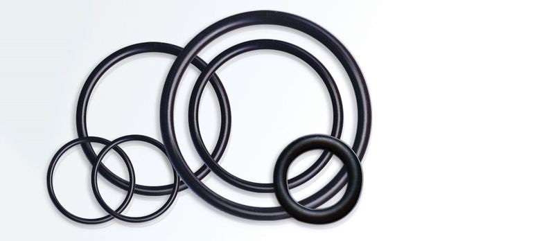
The O-Ring is the most widely adapted seal in history because of its simplicity, low cost, ease of installation, and small space requirements without supporting structures. It is suitable for dynamic or static seals within the temperature limits of elastomeric materials. Successful use depends upon proper groove dimensions and selection of the right Compound, or from one's prior experience with similar applications.
An O-Ring seals by distortion of its resilient, elastic compound to fill the leakage path. Figure 1-1 shows an O-Ring IMPROPERLY used. As installed, it is not deformed but retains its natural round shape. With the application of pressure as in figure 1-2, the O-Ring is likely to deform (as part of its design characteristic) to open a leakage path.
Figure 1-3 shows the proper installation of an O-Ring seal. (NEED PICTURE) Notice that the clearance for the O-Ring is less than its free outer diameter, that the O-Ring cross-section is squeezed diametrically out-of-round even before the application of pressure. This ensures contact with the inner and outer walls of the passage under static conditions. Figure 1-4 now shows the action of this properly installed 0-Ring when pressure is applied. Since both the inner and outer walls are in firm contact with the O-Ring material, the pressure tends to force it along its groove. Engineered to deform, the rubber compound flows up to the passage, completely sealing it against leakage. The higher the pressure trying to leak past, the tighter the seal that is thus formed. Upon release of the pressure, the resiliency of the rubber compound results in the O-Ring returning to its natural round form, undamaged and ready for similar cycles.
By this fundamental explanation, the criteria of design are clearly visible. The initial "diametral squeeze" is vitally important. An initial "diametral squeeze" of 10% results in a flat sealing surface of about 40 to 45% of the initial cross- section area of the O-Ring AT ZERO PRESSURE. Thus, at zero or very low pressures, the natural resiliency of the rubber compound provides the seal. It follows that very low pressure sealing may be improved by increased "diametral squeeze" (but note that such increased squeeze may adversely affect dynamic sealing at higher pressures). The "diametral squeeze" induces a frictional force between the O-Ring and the walls of the sealed passage that tend to hold the O-Ring in "neutral" position. Until the forces applied are sufficient to either overcome the frictional force or deform the rubber compound, the O-Ring will retain its initially deformed shape and will seal purely by diametral pressure.

Lorem ipsum dolor sit amet, consect etur adipisicing elit, sed do eiusmod tempor incidi dunt.
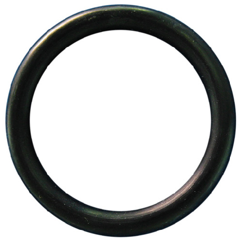
An elastomeric seal of homogenous composition molded in one piece to the configuration of a torus with circular cross-section (doughnut). The O-Ring is used as a dynamic or static seal usually installed in a machined groove.